Arduino Uno Pins : The L Led Arduino Lesson 1 Blink Adafruit Learning System : See the digital pins page for details on the functionality of the pins.
Get link
Facebook
X
Pinterest
Email
Other Apps
Arduino Uno Pins : The L Led Arduino Lesson 1 Blink Adafruit Learning System : See the digital pins page for details on the functionality of the pins.. First of alll, we should know which pins of arduino can be used for pwm purposes. See the table below for the usable pins, operating voltage and maximum resolution for some arduino boards. Connect the arduino to computer. So i do not understand which pins i can use. It also has 2 kb of sram and 1 kb of eeprom (which can be read and written with the eeprom library).
The arduino uno pins compatible with pwm are the pins 3, 5, 6, 9, 10 and 11. A great one explains… most developers believe blockchain technology is a game changer. After soldering connect the i2c module to arduino uno. As can be seen in the image that the arduino uno has on board voltage regulator which converts the 5volts into 3v3 volts. And the documentation says a4 and a5 pins can also be sda/scl.
Arduino Arduino Uno R3 Sharetechnote from www.sharetechnote.com The uno has in total three power pins of which one has a supply voltage of 3.3v and two pins provide 5v. So you have 6 pins where you can create a pwm, using the analogwrite() function. The arduino uno has a lot of different pins and therefore we want to go over the different kinds of pins. See the digital pins page for details on the functionality of the pins. The 14 digital input/output pins can be used as input or output pins by using pinmode(), digitalread() and digitalwrite() functions in. Secondary pins are mostly communications pins such as i2c and spi. Next open serial monitor from the icon on top right corner of arduino ide. And the documentation says a4 and a5 pins can also be sda/scl.
See the digital pins page for details on the functionality of the pins.
Arduino uno has 14 digital input/output pins (out of which 6 can be used as pwm outputs), 6 analog input pins, a usb connection, a power barrel jack, an icsp header and a reset button. The arduino uno uses the atmega328 microcontroller, which has an absolute maximum rating of 40 ma source or sink per gpio. A great one explains… featured on meta. Next open serial monitor from the icon on top right corner of arduino ide. Without interrupts your arduino would spend most of it's time just monitoring pins for activity and slow down the rest of your code. How to use arduino board. The 14 digital input/output pins can be used as input or output pins by using pinmode(), digitalread() and digitalwrite() functions in. Like a 9v battery or a wall adapter that is in the range of 7 to 12 volts. This pin of the arduino board is used to produce the external interrupt and it is done by the pin numbers 0,3,21,20,19,18. Overview using interrupts enables you to run some code only when a change happens on a pin. The analog pins can be used identically to the digital pins, so for example, to set analog pin 0 to an output, and to set it high, the code would look like. So if you will upload sketches to your uno, be sure to first disconnect any wires on pins 0 and 1. Internally, int0 is mapped to digital i/o pin 2 and int1 is mapped to digital i/o pin 3.
And, finally, the reset pin on the arduino uno is connected to the reset pin on pin 1 of the atmega328. There is a special function called attachinterrupt() in arduino, using which you configure the external interrupts. This can be quite useful to control some actuators that require a fine voltage tuning, and are not only switched on or off. This diagram shows the pinout location of the analog pins. This pin of the arduino board is used to produce the external interrupt and it is done by the pin numbers 0,3,21,20,19,18.
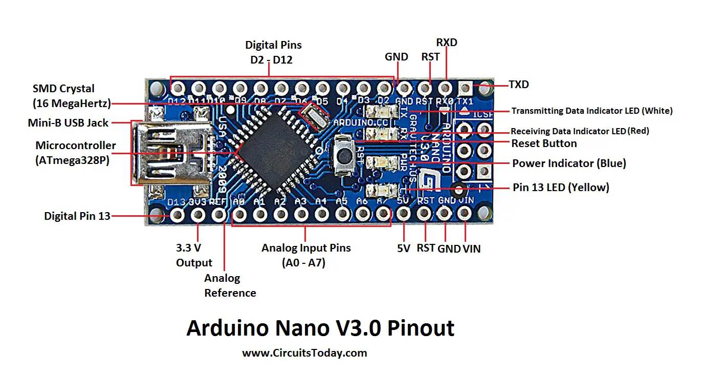
Arduino Nano Pinout Schematics Complete Tutorial With Pin Description from www.circuitstoday.com But the recommended current is 20 ma. That is 5 volt battery or power adapter can be connected to the arduino uno to deliver power through this pin. As of arduino 1.0.1, it is possible to enable the internal pullup resistors with the mode input_pullup. Arduino uno has 14 digital input/output pins (out of which 6 can be used as pwm outputs), 6 analog input pins, a usb connection, a power barrel jack, an icsp header and a reset button. I am trying to create an i2c communication bus with an arduino uno. A great one explains… featured on meta. The analog pins can be used identically to the digital pins, so for example, to set analog pin 0 to an output, and to set it high, the code would look like. This diagram shows the pinout location of the analog pins.
The 14 digital input/output pins can be used as input or output pins by using pinmode(), digitalread() and digitalwrite() functions in.
A great one explains… most developers believe blockchain technology is a game changer. First of alll, we should know which pins of arduino can be used for pwm purposes. All power pins have a maximum current of 50 ma. The arduino uno has a lot of different pins and therefore we want to go over the different kinds of pins. A great one explains… featured on meta. Let the numbering begin with the rx pin (d0). And, finally, the reset pin on the arduino uno is connected to the reset pin on pin 1 of the atmega328. It's important to note that: Internally, int0 is mapped to digital i/o pin 2 and int1 is mapped to digital i/o pin 3. Like a 9v battery or a wall adapter that is in the range of 7 to 12 volts. Examples barometric pressure sensor : Without interrupts your arduino would spend most of it's time just monitoring pins for activity and slow down the rest of your code. So i do not understand which pins i can use.
The board is equipped with sets of digital and analog input/output (i/o) pins that may be interfaced to various expansion boards (shields) and other circuits. Remember, there is already a 10k resistor attached to pin 1, you need to leave that in place. This can be quite useful to control some actuators that require a fine voltage tuning, and are not only switched on or off. First of alll, we should know which pins of arduino can be used for pwm purposes. The arduino uno board is divided into digital pins, analog pins and power pins.
Schematic And Input Output Pins Explain For Arduino Uno R3 Embedded Electrical Engineering Labs Yongjie from eelabs.files.wordpress.com The arduino uno uses the atmega328 microcontroller, which has an absolute maximum rating of 40 ma source or sink per gpio. How to use arduino board. These pins can be configured to work as input digital pins to read logic values (0 or 1) or as digital output pins to drive different modules like leds, relays, etc. I see on arduino uno there is twice sda and sdl: That is 5 volt battery or power adapter can be connected to the arduino uno to deliver power through this pin. The 2 first pins side to usb connector are sda/scl according to documentation. The uno has in total three power pins of which one has a supply voltage of 3.3v and two pins provide 5v. The total of all current op wants the gpio pins to sink, or source) is rated to a maximum of 150 200 ma.
That is 5 volt battery or power adapter can be connected to the arduino uno to deliver power through this pin.
This can be quite useful to control some actuators that require a fine voltage tuning, and are not only switched on or off. Digitalread() works on all pins on arduino uno.digitalread() will simply round the analog value received and present it to you.digitalwrite() has allowed parameter 0 or 1.analogread() works only with analog pins. I see on arduino uno there is twice sda and sdl: The arduino uno board has 14 digital i/o pins (15) (of which 6 provide pwm (pulse width modulation) output. Difference between analog and digital pins in arduino uno. The pins labeled ~ can be used to generate pwm. The header on the left side of the board has all these analog pins together. It also has 2 kb of sram and 1 kb of eeprom (which can be read and written with the eeprom library). A great one explains… featured on meta. The arduino uno pins compatible with pwm are the pins 3, 5, 6, 9, 10 and 11. This diagram shows the pinout location of the analog pins. The board is equipped with sets of digital and analog input/output (i/o) pins that may be interfaced to various expansion boards (shields) and other circuits. First of alll, we should know which pins of arduino can be used for pwm purposes.
There are pins with secondary functions as listed below arduino uno. This pin of the board is used for i2c communication.


Comments
Post a Comment